


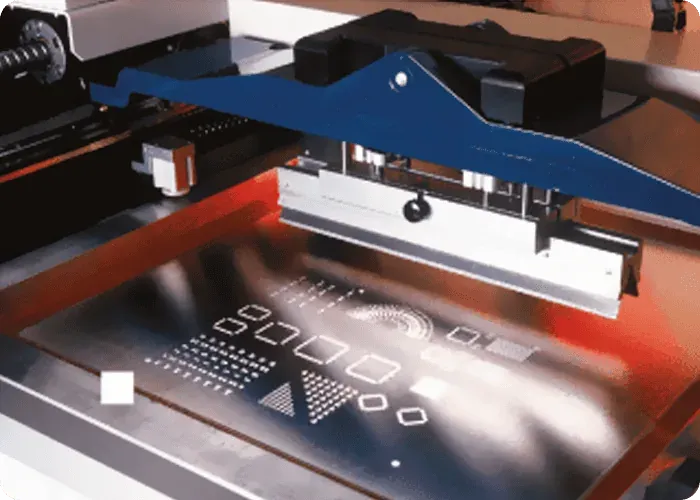
There is a gap in how stencils get validated. Incoming inspection confirms that the stencil was acceptable at the moment it shipped. Print consistency is a process variable that runs for weeks or months. A stencil that passed handoff can deposit something noticeably different on print 300 than it did on print 3, with nobody having touched the aperture data in between.
Almost all of that difference traces back to one thing — tension — and to the handling that happens around it. This article is not about how to choose a stencil (material, frame type and tension-management selection criteria are covered in stencil material, frame type and tension selection), and it does not revisit aperture geometry (area ratio and paste release). It answers one question only: once the foil is in the frame, what is physically happening, and how does it get lost?
Tension is not "pulled tight" — it is a springback budget
Correct one intuition first. Tension is not there to make the stencil look flat. It exists to give the foil a springback budget.
In one full print cycle the stencil deforms twice:
- Squeegee downforce. The blade sweeps paste across the foil and presses it down toward the board. Tension supplies the reaction force. When tension is low, the foil is pushed into a slight rolling bulge ahead of the blade, so the squeegee is working on a moving slope and the paste pressure over each aperture changes with it.
- Separation springback. At the instant the stencil parts from the board, the foil has to snap back to its original plane immediately and uniformly. That snap is the final mechanical action that pulls paste out of the aperture and leaves it on the pad.
Point 2 is the one that gets overlooked. Clean paste release is half aperture area ratio and half how crisply the foil springs back at separation. The 0.66-and-above area ratio you worked out at design time assumes the foil behaves as a rigid plane separating instantly and vertically. Once tension decays, springback slows and goes locally out of sync, and the real release behaviour is no longer the one the design assumed.
This explains a very common complaint: not a single aperture was changed, the paste is from the same lot, and yet insufficient deposits and offset prints start appearing. What changed is not the design. It is the mechanical premise the design rests on.
Gasketing: tension's second job
Tension also governs something unrelated to release: whether the stencil underside seals against the board.
If a gap exists between the stencil bottom and the pads during printing, paste squeezes sideways under pressure and leaves a skirt of bleed around the pad. That tight contact is called gasketing, and three things decide it together: whether tension keeps the foil in contact under squeegee pressure, whether the foil itself is flat, and whether the board is flat.
Note the last item. Board flatness is an input to stencil gasketing. This cross-process link is regularly missed: when incoming bare-board bow and twist run outside the allowed range, the symptom that shows up on the print line is usually reported as "the stencil is bleeding", not "the board is not flat". Board flatness and outline tolerances are PCB-side metrics — see manufacturing tolerance standards. So a print-defect investigation cannot close the loop inside the stencil and printer alone.
Framed vs unframed: who owns tension is a completely different answer
SKPCB's SMT stencil service offers both framed (glue-in) stencils and unframed foils, and the page states the positioning difference: framed stencils carry a permanent frame with a mesh border tensioning the foil, aimed at high-volume, long-run, high-precision use; unframed foils have no permanent frame, fit into reusable frames, and are aimed at short runs, low volume and prototypes.
Read in terms of tension ownership, those two sentences matter far more than the price difference:
Framed — tension is built into the product at the factory. The foil is bonded and tensioned to an aluminium frame through a mesh border and ships already at its target state. Which means:
- you neither need to nor can adjust tension when mounting;
- tension consistency is the supplier's responsibility, and the line only has to mount it correctly;
- the price of that is that once tension decays there is no remedy — the stencil is rejected and replaced. The mesh and the bond line, not the stainless foil, are what actually determine this stencil's service life.
Unframed — tension happens in your shop, and happens again every single time it is mounted. That has a structural consequence:
- the same foil can sit at a different tension state across shifts and operators;
- so print consistency on an unframed setup is really a function of how repeatable the mounting action is, not of foil quality;
- the flip side is the advantage: tension state is resettable. A foil mounted badly is fixed by releasing and remounting.
This distinction sets the direction of any investigation. When a framed stencil starts drifting, suspect the stencil first (mesh creep, bond line, foil deformation), because the line has almost no variables to change. When an unframed foil starts drifting, suspect the mounting first, because that is the step redone at every setup and the largest source of variation. Getting these two orders backwards costs a full shift.
Three paths to in-service failure
Stencils do not fail suddenly. They drift away from their shipped state along three independent paths, and the three differ in symptom, reversibility and who owns them.
Path 1: mesh and bond-line creep (framed stencils only)
A tensioned mesh carries sustained tensile load and the bond line carries sustained shear. Both relax slowly with time and temperature. The signature is:
- Gradual, irreversible, global. Tension drops as a whole; nothing breaks in one spot.
- Symptoms appear first at the position farthest from the frame edge — the middle of the stencil, where the free span is largest and tension loss is amplified most.
- Visually almost undetectable. That is the dangerous part: mesh intact, foil unbroken, apertures clear, stencil looks entirely normal.
Path 2: local plastic deformation of the foil (framed and unframed)
This path is almost entirely handling-induced, and mostly happens away from the printer:
- fingers or tools pressing on the foil during pick-up and put-down;
- knocks against hard objects, or load taken on an edge;
- stacking flat, or being crushed by other items in vertical storage;
- wiping one area hard during cleaning, especially over fine-pitch apertures.
The signature is local, sudden, irreversible. One small region prints badly and the rest is fine. The pattern "the same component position is repeatedly starved, changing boards makes no difference, changing stencils fixes it" is essentially always local deformation.
Path 3: aperture residue accumulation (framed and unframed)
This path does not change tension. It changes the effective area ratio. Dried paste, flux residue and cleaner residue on the aperture walls steadily shrink the usable cross-section — the 0.66 you calculated is a geometric value, while the one that actually governs is the value left after residue is subtracted.
This is why wipe frequency has to be a line parameter, not a stencil parameter. SKPCB's stencil service page lists optional nano-coating whose stated purpose is to cut aperture residue and extend wipe intervals — but it relaxes the interval, it does not remove cleaning. Treating nano-coating as "no cleaning needed" just lets this path run to its end more slowly and just as certainly.
Of the three, only path 3 is reversible — a thorough clean restores it. That gives you the first branch point in any investigation: clean thoroughly once. If printing recovers, it was residue. If it does not, then go look at tension and deformation.
Do not judge a stencil by looking at it — use print evidence
Two of the three paths above are invisible. Which produces the most practical conclusion in this article:
> A change in stencil condition shows up in paste deposition before it shows up in stencil appearance.
So the call on whether a stencil is still usable is not made by eye. It is made with the inspection chain already sitting on the assembly side. In SKPCB's PCBA assembly flow that chain is complete: SPI (solder paste inspection) → inline 2D AOI → post-reflow 3D AOI → X-ray → ICT / FCT, with IPC-A-610 Class 3 as the acceptance criterion, hidden joints such as BGAs checked against a <10% voiding figure (nitrogen reflow), and 100% electrical test on finished boards.
SPI is the only step in that chain that observes stencil output directly, and the only one that can catch a stencil problem before components are placed on top of it. Its position defines its value: everything after SPI sees a combined result of paste plus placement plus reflow, and attribution gets far harder.
Reading stencil condition from SPI means watching distribution drift, not single out-of-spec events:
| Observed pattern | Most likely path | Do this first |
|---|---|---|
| Deposits down across the board, worse at centre than edges | Path 1 (mesh creep) | Check tension; prepare to reject — framed cannot be fixed on the line |
| A few fixed positions repeatedly low, unchanged by new boards | Path 2 (local deformation) | Inspect the foil in that region for a knock or press mark |
| Deposits decline slowly with print count, recover after cleaning | Path 3 (residue) | Adjust wipe frequency, review the cleaning method |
| High and low across regions of one board, different at every setup | Mounting not repeatable (mostly unframed) | Standardise the mounting method before touching the stencil |
| Bleed, paste skirting outside the pad | Poor gasketing | Check tension and incoming board flatness together |
The value of the table is that it splits the vague symptom "it prints badly" into branches with clear ownership. Starved deposits eventually land on the joint, and the causal grouping of common joint failures is covered in PCBA solder joint failure causes; what to verify at incoming and what the handoff sheet should freeze is in stencil incoming inspection and handoff. This article covers the stretch after that handoff.
Where responsibility splits: shipped state vs in-service state
Condensing the above into one actionable line:
Shipped state (stencil supplier owns)
- Foil delivered tensioned to its target state: framed stencils arrive already tensioned; unframed foils are delivered to the clamping requirements of the reusable frame.
- Sampling of critical aperture dimensions and positional deviation.
- Fiducials clean and burr-free.
- Aperture data governed by engineering review — SKPCB's stencil service page states explicitly that the released data after engineering review governs the actual apertures, and that table values are common reference ranges.
In-service state (the line owns, and only these three are controllable)
- Mounting repeatability. Whether tensioning and locating are done the same way at every setup. Unframed foils depend on this above all.
- Cleaning and wiping. Frequency is a line parameter, tuned to paste, pad density and coating; it is not a shipped property of the stencil.
- When the call is made. Judge from SPI distribution trend rather than waiting for AOI or post-reflow to surface it.
No figures are given here: tension values, snap-off distance, cleaner and dilution, print-count life and mesh specification all have to be confirmed by engineering review against the equipment, paste and board design. The industry design and acceptance frameworks referenced are IPC-7525 (stencil design) and IPC-A-610 (assembly acceptance) — industry standards, not SKPCB internal windows. The stencil specification ranges SKPCB does publish (construction, materials, foil thickness, common frame sizes, polishing and coating options, input files) are on the stencil service page and manufacturing capabilities; the quality system and inspection methods are on quality assurance. To price a stencil together with assembly, use the quote request.
FAQ
Q1. What should the tension be? Is there a universal number?
No number here, because no universal one exists. The right tension state depends on foil type and thickness, frame size, paste characteristics, squeegee pressure and speed, and aperture density on the board. IPC-7525 is the common industry reference framework for stencil design and use; actual values must be confirmed by engineering review against your equipment and process. Borrowing another shop's tension figure means borrowing a different set of premises.
Q2. Can a framed stencil's tension be restored in the shop?
No. On a framed (glue-in) stencil the foil is bonded and tensioned to the frame through a mesh border, fixed at the factory, with no adjustment interface on the line. A framed stencil whose tension has decayed is rejected and replaced. If your situation needs resettable tension, that is a selection-stage decision — see stencil selection.
Q3. My aperture data has not changed, so why did printing suddenly get worse?
Because area ratio is a geometric design value, while what actually governs is the value after aperture residue is subtracted and after the foil's real springback behaviour is taken into account. Tension decay changes separation springback, residue accumulation changes effective aperture size, and neither requires a data change to push results away from the design. Order of investigation: clean thoroughly once to rule out residue; if it does not recover, look at tension and local deformation.
Q4. Does nano-coating mean cleaning is no longer needed?
No. The coating reduces aperture-wall residue and extends wipe intervals. It relaxes the frequency; it does not eliminate cleaning. Used as a no-clean solution, the residue path still runs to its end, just more slowly.
Q5. The stencil looks fine — can I assume it is fine?
No. Of the three in-service failure paths, mesh creep and most local deformation are not visible; what the eye reliably catches is blocked apertures and gross damage. The dependable criterion is print evidence, particularly the distribution trend of SPI deposits — see the inspection chain in the PCBA assembly flow.
Q6. I am getting bleed around the pads. Is that low stencil tension?
Low tension is one cause, not the only one. Bleed points to poor gasketing, which three things decide together: tension, foil flatness, and the flatness of the board itself. So check whether incoming board bow and twist are inside the allowed range as well — the relevant metrics are in manufacturing tolerance standards. Looking only at the stencil may well find nothing.
Q7. Are unframed foils inherently less consistent than framed stencils?
Not inherently worse — the source of variation is different. Unframed tensioning happens on the shop side and happens again at every setup, so consistency depends on whether the mounting action is repeatable. Standardise the mounting well and unframed is stable; fail to, and no foil quality will save the print. This is also why an unframed setup that starts drifting should have its mounting checked before the stencil is suspected.
Q8. One board has large connector pads and fine-pitch parts. Can tension solve the deposit-volume difference?
No. Mixed deposit requirements on one board are an aperture-and-thickness zoning problem, which falls under step stencil design — see step stencil multilevel aperture design. Tension governs springback and gasketing across the whole foil; it provides no zoning capability.