


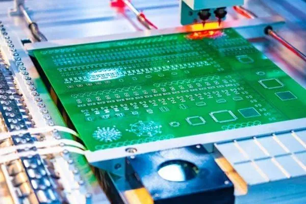
Two kinds of print defect, and only one responds to machine settings
When paste volume goes low or pads bridge, the reflex on most lines is to change squeegee pressure. That works about half the time. The other half it does nothing and moves the problem somewhere harder to diagnose.
The test for which half you are in is simple: are the failures scattered across positions and boards, or does the same position fail on every board?
- Variation inside the window: defects move around, improve after a paste change or a stencil wipe, differ board to board. The process window is too narrow. Machine settings help.
- Failure outside the window: the same pad, in the same array position, fails on every board. That aperture cannot print acceptably with this stencil on this board, and continuing to adjust the machine only degrades every other position.
This article handles the first kind. Section seven tells you how to identify the second kind and where it goes instead.
The precondition: with a gap under the stencil, squeegee settings are noise
Physically, stencil printing does three things. The squeegee pushes paste into apertures. The paste packs into the aperture. When the stencil lifts, the paste stays on the pad instead of on the aperture wall.
The condition most often assumed rather than verified is the one behind step two: no gap between the underside of the stencil and the board surface. With a gap, paste spreads sideways under squeegee pressure and lands outside the pad. That is where under-stencil smearing and "printed deposits larger than the aperture" come from. Squeegee pressure is involved, but it is not the root cause.
So diagnosis starts at gasketing. A usable check is to look at the stencil underside. Broad paste tracks there, rather than light residue immediately around apertures, means gasketing has failed. Adjusting the squeegee at that point is compensating one variable with another, and the window narrows with every iteration.
Variable group one: the squeegee, three parameters and two standing conflicts
Three squeegee-side quantities get adjusted. Each controls something different, and they work against each other.
- Angle sets the ratio between the force pushing paste down into apertures and the force pushing it forward. A steeper blade puts more force downward and fills more completely, at the cost of harder wiping against the foil.
- Pressure sets how cleanly the foil is wiped and how firmly the stencil is pressed to the board. Too little and paste stays on the foil, where the next stroke deposits it somewhere it does not belong. Too much and the blade begins to scoop apertures, removing paste that was already packed, so fine-pitch areas end up with less paste, not more, while blade and foil wear accelerate.
- Speed sets how much time paste has to flow into an aperture. Faster strokes fill deep apertures less completely. But too slow and paste dwells in front of the blade, its viscosity shifts under shear, and small apertures get harder to fill rather than easier.
Two conflicts are permanent. Pressure fights fine-pitch filling — raise it and small apertures get scooped. Speed fights large-aperture filling — slow it down and large deposits slump at the edges. Squeegee settings are therefore not an optimum to find but a band both ends of the board can live with. The finest pitch on the board decides how narrow that band is. SKPCB's PCBA process supports a minimum pitch of 0.2 mm on BGA and 0.3 mm on QFN/QFP (CLAIM_REGISTER: PCBA-PITCH) with a smallest placed component of 01005 (PCBA-MIN); boards at that level have a visibly narrower squeegee band than ordinary mixed-technology assemblies.
Variable group two: separation, where paste is pulled out rather than dropped out
At the instant the stencil lifts, paste in the aperture is held by two competing adhesions: the aperture wall and the pad. Paste stays on the board only when the pad wins.
That explains two things lines routinely get backwards.
- Slower separation is not automatically better. Too slow and the paste has time to retract along the wall, the edges stay behind, and the deposit comes out short and slumped. Too fast and the paste tears, leaving part of it in the aperture. What works is a slow initial break over a short distance, then acceleration away — not a single speed throughout.
- Separation problems get misread as fill problems. Under-filled apertures were never full, so the deposit is short but complete and flat on top. Poor separation means the aperture was full and only part of it came out, so the deposit is notched or conical on top. Deposit shape distinguishes the two; volume alone does not.
Wall condition and foil tension both shift this balance. Rougher walls and uneven tension both degrade separation consistency. Both are properties of the stencil, not of the printer.
Variable group three: support and clamping, three board types and three different problems
Support is the group most often skipped and the one that sets how wide the window can be. A board held evenly lets all squeegee pressure go into filling apertures. A board that is not held evenly turns part of that pressure into board flex.
Three situations, three distinct problems:
- Thin boards bow downward in the middle under the blade, opening a gap between stencil and board. The signature is systematic smearing or paste loss in the board centre while the edges print normally. This needs dedicated support, not just edge rails.
- Panel arrays are less stiff at the connections — mouse-bites or V-cut — than at the centre of an individual board, so flex is uneven and deposit volume differs between boards within one array. Array layout and connection type are board-side inputs that have to be fixed before the stencil is ordered.
- Second-side printing over placed components rules out flat tooling plates; clearance support is mandatory. Wrong support positions either press on soldered components or lift the board locally around them. Large components make this sharper: SKPCB's PCBA process handles BGA/QFP up to 74 mm diagonal (PCBA-MAXCOMP), and second-side support on a face carrying parts that size has to be planned, not improvised.
Clamping exists to stop the board moving along the squeegee travel direction. Under-clamped, the first stroke shifts the board by a small amount, every deposit sits offset from its pad, and it looks like stencil misalignment when the board actually moved. Check whether the offset direction matches the squeegee travel direction.
The adjustment order: fixed, not interchangeable
The order exists because each step is a precondition for the next. Skip a step and later parameters end up compensating for an earlier defect, which is exactly how a window gets narrower each shift.
- Support: confirm the board is held evenly; use the matching scheme for thin boards and second sides.
- Gasketing: confirm no gap between stencil underside and board, and a clean underside.
- Squeegee: set angle, pressure and speed within a band that both the finest and the largest apertures on this board accept.
- Separation: set a slow-break-then-accelerate profile, judged by deposit shape rather than volume.
- Wipe interval: fix how many boards run between underside wipes. The interval is part of the window, not a maintenance item — set it too long and the back half of the batch is not the same process as the front half.
After each step, re-confirm the previous one still holds instead of running the whole sequence and checking at the end.
Five defects to stop adjusting the machine for
These sit outside the window. The root cause is in stencil design or the data package, and further machine adjustment only hides them at the expense of other positions.
- The same pad is short of paste on every board, and that pad is clearly smaller than its neighbours — aperture area ratio is insufficient and the paste cannot geometrically release. The fix is aperture-to-foil matching: see aperture area ratio and paste release.
- Connector pads want more paste while fine-pitch parts want less, and one thickness serves neither — a local thickness conflict that has to be judged as a step-stencil decision: see the step-stencil decision.
- Separation consistency differs noticeably between regions of the foil — tension distribution or foil material: see stencil material, frame and tension.
- Every deposit is rotated or scaled relative to its pad — datum, array or fiducial mismatch between stencil and board, which is a data package issue: see stencil data package fields.
- A new stencil prints poorly from its first run and behaves differently from the previous stencil of the same artwork — an incoming condition issue that belongs in inspection, not on the printer: see stencil incoming inspection and handoff.
First-article release: what has to be frozen for the window to be repeatable
A window is only repeatable once its inputs are frozen. At first-article release, record and freeze the support scheme including second-side clearance positions, stencil identification and revision, squeegee angle/pressure/speed, the separation profile, the wipe interval, and the first-article measurement result.
The measurement loop is carried by SKPCB's PCBA test capability: SPI for post-print volume and offset, in-line 2D AOI plus post-reflow 3D AOI, X-Ray, ICT and FCT for the stages after it (CLAIM_REGISTER: PCBA-TEST). Assembly acceptance follows IPC-A-610 Class 3 (PCBA-IPC), and solder voiding is controlled below 10% under nitrogen reflow (PCBA-VOID). Judge the print window on SPI data, not on post-reflow joints — by then the reflow profile is mixed in and the result can no longer be attributed to printing alone.
Inspection and release arrangements are set out on quality and inspection; assembly process capability is on PCBA assembly capability.
Print-side inputs to supply before quoting and first build
These come from design or process engineering. Each one missing is one more thing the line has to guess at by adjusting the machine:
- Finest pitch and smallest pad on the board, and where they sit
- Board thickness, and whether it counts as a thin board needing dedicated support
- Array layout, array count and connection type
- Print sides, and the height and position of components already placed on the second side
- Any local thick-deposit requirements: connectors, shield frames, high-current pads
- Expected volume and changeover frequency, which drive the wipe interval and foil material direction
Stencil fabrication and related services: SMT stencil fabrication.
FAQ
What squeegee pressure should I use?
There is no number to copy. The acceptable pressure band is set jointly by the finest and largest apertures on your board and shifted by the support scheme. We do not publish a recommended value because a pressure figure detached from a specific board does nothing on the line. Work the order in section six: once support and gasketing hold, converge the band using results from both the finest and the largest apertures.
Paste volume is low. Pressure first, or speed first?
Neither is first. Check the stencil underside for broad paste tracks (gasketing) and compare board centre against board edge (support). With those cleared: if the loss concentrates in fine-pitch areas, reduce pressure before speed; if it concentrates at large apertures, reduce speed first.
How do I tell under-filling from poor separation?
By deposit shape. Under-filled deposits are short, complete and flat on top. Poor separation leaves deposits notched, conical, or with lifted edges. Volume is low in both cases, so SPI volume judgment alone cannot separate them.
Is clearance support always required for second-side printing?
Yes, whenever components are already placed on the underside. A flat plate either presses on soldered parts or lifts the board locally around them, and both destroy stencil-to-board contact. Clearance positions have to be derived from the component layout during program preparation, not shimmed at the machine.
How often should the stencil underside be wiped?
The interval is part of the process window. It depends on board type, aperture density and how paste behaves on the foil, so it is determined at first article and then frozen. The thing to avoid is treating it as a maintenance item that can be stretched — change the interval and the back of the batch is no longer comparable to the first article.
Can every print problem be solved at the printer?
No. The five cases in section seven are rooted in stencil design or the data package, and further adjustment trades other positions away to mask them. The deciding question is whether the defect repeats at the same position on every board. If it repeats, it is outside the window and goes back to design or incoming inspection.