


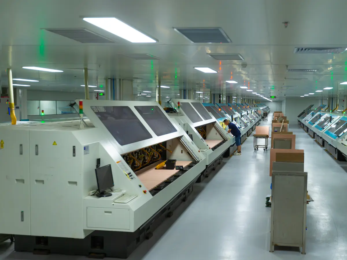
Mechanical drilling is the first step after lamination that cuts through every layer of a multilayer board. In one pass the drill goes through copper foil, glass cloth and resin, three materials that respond very differently to a cutting edge. Whatever roughness, smear and burr the hole wall gets at this moment is inherited unchanged by desmear, electroless copper and electroplating.
Acceptance criteria for drilled holes are covered in our separate article on PCB drilling quality inspection. This article stays inside the drilling step: which process variables decide hole wall quality, and how a fabricator keeps them under control before release.
1. Where drilling sits in the process
A typical multilayer flow runs: inner-layer imaging → oxide treatment → lamination → drilling → desmear → electroless copper → electroplating → outer-layer imaging.
Drilling sits between lamination and hole metallization, which has two consequences:
- Lamination has already introduced scaling and layer-to-layer shift, so the drill has to hit inner-layer pads that have moved.
- Drilling defects are covered by copper after plating and often only show up in a microsection or after thermal stress.
That is why most drilling problems leave the factory unseen unless they are controlled inside the process rather than caught afterwards.
2. Drill bit wear and hit count
The cutting edge of a drill bit dulls with every hole. A dull edge no longer shears the glass fibres cleanly; it pushes and tears them. The result is a chain of defects:
- Rough hole walls: pulled glass and torn resin leave an uneven wall that plates into copper nodules or thin spots.
- Nailheading: the dull edge smears inner-layer copper into the hole, which looks like a nail head in cross section.
- Heat and resin smear: friction raises the temperature, resin softens and smears across the inner-layer copper, weakening the connection between barrel copper and the inner layer.
- Hole size drift: wear makes holes gradually undersized or out of round.
Fabricators set a maximum hit count for each drill diameter and material and change the bit when it is reached. Some bits can be resharpened, but the number of regrinds is also limited. The actual limits depend on laminate, board thickness, hole size and stack, so there is no universal figure. High-Tg, filled and high-frequency laminates wear bits faster and need tighter limits.
3. Stack height and board thickness
Thin boards are often drilled several panels at a time. The taller the stack, the longer the drill and the more it deflects:
- Hole position drift: the bit wanders as it goes down, so the bottom panel has the largest position error.
- Exit burrs: the bottom panel has the least support at the exit, which produces the most burrs and lifted copper.
- Poor chip evacuation: deeper holes clear debris less easily, heat builds up and smear increases.
Thick boards, high layer counts and small holes are usually drilled one panel at a time, sometimes with step drilling. Stack height is a trade-off between position accuracy and throughput, set by engineering according to thickness, hole size and accuracy requirements.
4. Entry and backup boards
An entry board sits on top of the panel and a backup board underneath.
- Entry board: gives the drill a clean starting point so it does not skate on copper, suppresses entry burrs and helps carry heat away. Aluminium sheet or coated composite boards are common.
- Backup board: supports the exit side of the bottom panel to limit exit burrs, and lets the drill break through fully without touching the machine table.
Both are consumables. Reusing them defeats their positioning and support function, and an unsuitable backup material can drag debris back into the hole.
5. Feed, speed and chip evacuation
Feed rate (depth per revolution) and spindle speed together set the cutting load:
- Feed too high: high cutting force, more deflection, broken bits and torn walls.
- Feed too low: the bit rubs in the hole longer, temperature rises and smear increases.
- Wrong spindle speed: small drills need high spindle speeds to reach a proper cutting speed; too little speed also tears the wall.
- Peck drilling: deep holes can be drilled in steps with retracts to clear chips and limit heat.
Parameters are kept in process tables by drill diameter, laminate and thickness, and are not changed ad hoc on the shop floor.
6. Defects and their causes
| Defect | Main cause | Downstream effect |
|---|---|---|
| Rough wall, protruding glass | Bit wear, wrong feed | Uneven barrel copper, nodules, wicking |
| Nailheading | Dull bit, hit count exceeded | Stress concentration at inner-layer joints |
| Resin smear | Excess heat, poor chip evacuation | Inner-layer separation from barrel |
| Entry burr | Missing or worn entry board | Uneven pad edges, solder mask defects |
| Exit burr, lifted copper | Weak backup support, tall stack | Bottom-side pad defects |
| Hole position drift | Tall stack, bit deflection, lamination scaling | Breakout, weak inner-layer connection |
| Broken bit, missing hole | Overload, defective bit | Open circuit, found by electrical test |
Desmear removes part of the smear but cannot repair a badly torn wall. Controlling the drilling step is more reliable than relying on later process steps to compensate.
7. How drilling is controlled before release
- Process tables and bit management: parameters and hit count limits per diameter and laminate; the drilling machine counts hits and changes bits automatically, and reground bits carry their own life record.
- First-article check: the first panel of each lot is checked for hole size, hole count and position to confirm program and tooling.
- Broken-bit detection: the machine detects a broken drill, and the missed holes are located and redrilled.
- Position and size checks: sample checks of how holes land on inner-layer pads. SKPCB's standard hole position accuracy is ±0.05 mm; hole size tolerance is ±0.075 mm for PTH and ±0.05 mm for NPTH.
- Microsection sampling: after plating, samples are cross-sectioned to check wall roughness, nailheading and residual smear, judged to the applicable IPC-6012 class (SKPCB supports Class II and Class III).
- 100% electrical test: SKPCB tests every order electrically, which catches missing holes and open barrels.
8. What the design side can do
- Use fewer hole sizes: every extra diameter means more tool changes and less room to optimise parameters for each one.
- Stay off the capability floor: SKPCB's standard minimum mechanical hole is 0.2 mm with a maximum aspect ratio of 10:1; smaller holes or higher ratios need engineering review.
- State finished hole sizes and tolerances on the drawing: separate PTH and NPTH, and call out press-fit holes on their own.
- Name the laminate: high-Tg, high-frequency and filled materials change drilling parameters and cost.
- Leave enough annular ring: allow margin for lamination scaling and drill drift.
If you want to confirm that a combination of hole size, board thickness and material suits standard drilling, submit the design for a free DFM review.
FAQ
Q: Is the hit count limit for a drill bit a fixed number?
A: No. It depends on hole size, laminate, board thickness and stack. High-Tg, filled and high-frequency materials wear bits faster and usually get lower limits.
Q: Can desmear make up for poor drilling?
A: Only partly. Desmear removes resin residue from the wall but cannot repair torn glass or a badly roughened wall.
Q: Why does the bottom panel in a stack have the largest position error?
A: The drill deflects more the deeper it goes. The bottom panel is furthest from the entry point, so the error accumulates there, and its exit side has the least support.
Q: Can drilling defects be found before shipment?
A: Missing holes and open barrels are found by 100% electrical test. Wall roughness, nailheading and smear need microsection inspection.