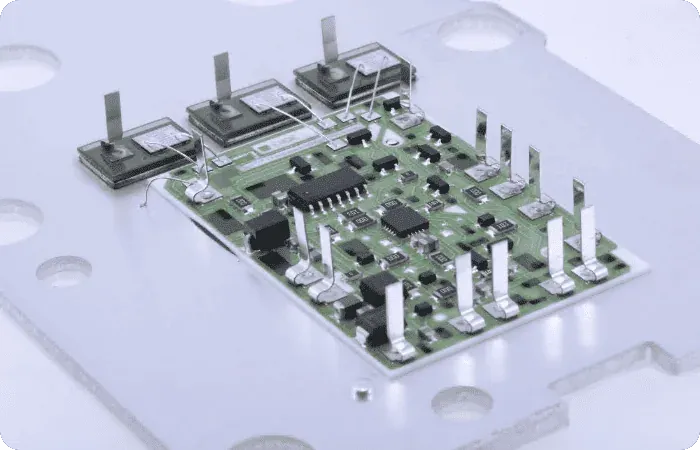
When FR-4 cannot carry the heat away, the usual candidates are an aluminum IMS (insulated metal substrate), a copper-base board and a ceramic substrate. All three move heat from the component toward the heat sink, but the heat takes a different path through each, and a different constraint limits each one. Checking the constraints one at a time and seeing which candidate drops out first is more reliable than comparing a single thermal-conductivity figure.
How the three substrates are built
| Item | Aluminum IMS | Copper base | Ceramic |
|---|---|---|---|
| Build | Copper foil / polymer dielectric / aluminum plate | Copper foil / polymer dielectric / copper plate; also pedestal builds where the thermal pad connects straight to the copper base | Metal layer formed directly on Al₂O₃, AlN or Si₃N₄ |
| Thermal bottleneck | Polymer dielectric | Polymer dielectric (bypassed by a pedestal) | The ceramic itself and the solder interface |
| Insulation | Thickness and material of the dielectric | Same as aluminum; at a pedestal, the pad shares the base potential | The ceramic body insulates |
| CTE match to silicon | Poor | Poor | Good; AlN and Si₃N₄ are closer to silicon |
| Outline machining | Routing, punching, V-cut | Routing, with more tool wear than aluminum | Brittle; dicing or laser |
| Relative cost | Low | Medium | High |
Machining and assembly differences between aluminum and copper are covered in Aluminum or Copper Base for Metal Core PCB.
Constraint one: heat flux density
Start with the heat flux under the component pad: power divided by pad area, not total board power. An LED strip spreads its heat over a large area, so the heat can spread sideways in the copper before it crosses the dielectric, and aluminum IMS is usually enough. A single high-power die or a dense cluster of power devices concentrates the heat. The polymer dielectric then becomes the dominant resistance, and a higher-conductivity dielectric lowers the temperature less than its datasheet suggests. The reason is explained in the thermal resistance chain of high-conductivity aluminum PCBs.
Concentrated heat leaves two routes. A copper-base pedestal solders the thermal pad directly to the metal base and bypasses the dielectric. A ceramic substrate removes the polymer layer altogether.
Constraint two: dielectric withstand voltage
On aluminum and copper base, the polymer layer carries all the insulation. A higher withstand requirement means a thicker dielectric and a higher thermal resistance, so heat transfer and insulation compete for the same layer. A copper pedestal puts the thermal pad at base potential, so it only works where the component thermal pad is unconnected or may be grounded.
On ceramic, the substrate body insulates, and withstand voltage and heat transfer no longer compete for one layer. This is why high-voltage power modules mostly use ceramic. The inputs a withstand test needs are listed in hipot test inputs for metal-base PCBs.
Constraint three: CTE match and thermal cycling
Aluminum and copper both expand far more than silicon dies and ceramic packages. With small parts and compliant joints this matters little. With bare-die attach, large ceramic packages or severe temperature cycling, the solder layer accumulates fatigue. In those applications a copper base can pass on thermal resistance and still lose to ceramic on cycling life. Choosing within ceramic (Al₂O₃ or AlN, DPC or DBC) is covered in Ceramic PCB Selection.
Constraint four: size, outline and layer count
Aluminum handles long strips and large panels and can be V-scored, which suits lighting and power supplies. Copper base costs much more in weight and material, and the gap grows with size. Ceramic is brittle, its outline and holes are made by dicing or laser, the board size is bounded by the ceramic sheet, and it does not suit mounting points that carry mechanical load.
Order of elimination
- Chip-level CTE match or high withstand voltage, with concentrated heat: look at ceramic first.
- Concentrated heat, and the thermal pad may share base potential: look at a copper-base pedestal build.
- Distributed heat, long or large boards, cost-sensitive: look at aluminum IMS.
- If aluminum still runs too hot, compare copper base against a higher-conductivity dielectric, and verify both with measured thermal resistance.
What to state in the RFQ
- Component power, thermal pad size, allowed junction or pad temperature
- Withstand voltage requirement and test condition; whether the thermal pad may be grounded
- Temperature range and cycle count for thermal or power cycling
- Board size, outline method, mounting method and flatness of the heat-sink contact face
- Layer count, copper weight and surface finish
How SKPCB handles it
During engineering review, SKPCB checks the substrate type, dielectric, copper weight and outline method against these conditions. The available range for each substrate is on the Metal Core PCB, Aluminum PCB and Ceramic PCB product pages. Once the conditions are complete, you can request a quote.
Summary
Distributed heat points to aluminum IMS. Concentrated heat points to a copper pedestal or ceramic. High withstand voltage and chip-level CTE match point to ceramic. Thermal conductivity is one number among several: rule candidates out with heat flux, withstand voltage, CTE and machining, then compare what remains.
FAQ
Q: Does a higher-conductivity dielectric always lower the temperature proportionally?
A: No. Temperature rise depends on the whole resistance chain, and with distributed heat the dielectric is not always the largest resistance.
Q: Does copper base always cool better than aluminum?
A: Copper conducts better than aluminum, but a standard copper-base board still sends heat through the same kind of polymer dielectric. The clear difference comes from pedestal builds that connect the pad straight to the copper.
Q: When is ceramic the necessary choice?
A: When high withstand voltage meets concentrated heat, or with bare-die attach and demanding thermal cycling.
Q: What limits a copper pedestal board?
A: The component thermal pad shares the base potential, so it must be unconnected or allowed to be grounded.
Q: Can ceramic substrates be made in large sizes?
A: Size is bounded by the ceramic sheet and the outline is diced or lasered. Long strips are usually aluminum.
Q: How should the choice be verified?
A: Test thermal resistance on the real build (for example with the ASTM D5470 method) and run a withstand test, rather than comparing material datasheets.